Thick Al ribbon bonding is applied to packaging of heavy duty power devices such as IGBT (Insulated Gate Bipolar Transistor) modules to secure high power density and to improve power controlling. These are very important for green innovations. Numerical studies of wire bonding give an informative result which cannot be obtained by any experimental method. The Al ribbon bonding is affected by temperature rise of bond-area and ribbon deformation. The temperature rise is related with frictional slip behavior at the bond-interface. In the present study, a simple numerical model of the ultrasonic Al ribbon bonding is proposed. The heat conduction between the Al ribbon and tool (substrate) is modeled to estimate the temperature rise during bonding, i.e., the temperature change and distribution of the bond area is visualized. The influence of interfacial thermal resistance and the boundary condition on the temperature rise is numerically examined.
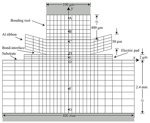
Figure 1 shows the mesh pattern of the bonding tool, Al ribbon, Al electric pad, and Si chip (or SiO2 substrate). The bonding tool is made of WC. The model is two dimensional and the heat flow in the z direction (perpendicular to the space) is ignored because the length of substrate in the z direction is 10 times greater than the thickness of substrate (2.4 mm) and the bottom of substrate is assumed to be kept at 300 K (in contact with a large heat sink). Two boundary conditions were given to the top of the bonding tool; 1) at 300 K and 2) J = 0 in the y direction, where J is the heat flux. It was assumed that the heat generation (heat input) at the bond-interface is produced by the friction slip at the bonding interface, i.e., the ultrasonic power of 4W was given to the elements adjacent to the bond-interface and the bonding area is 1mm x 100![]() m. The heat input per unit volume and unit time was 4.0x10⁻⁹Jm-3s-1. The heat input was supplied only to the elements in contact with the bond-interface in proportion to the volume of each element. Calculation of plastic deformation of Al ribbon was carried out by using a finite element method. Strain-rate-depending large plastic deformation was taken into account. The tool and the substrate were assumed to be rigid bodies. The thin pad film was neglected for plastic deformation. We assumed that the interface between tool and ribbon was fixed but the interface between ribbon and substrate was able to slip. We adopted three slip conditions; 1) free slip, 2) frictional slip, and 3) fixed. It was assumed that the frictional slip was produced uniformly on the bond-interface and the local frictional coefficient
m. The heat input per unit volume and unit time was 4.0x10⁻⁹Jm-3s-1. The heat input was supplied only to the elements in contact with the bond-interface in proportion to the volume of each element. Calculation of plastic deformation of Al ribbon was carried out by using a finite element method. Strain-rate-depending large plastic deformation was taken into account. The tool and the substrate were assumed to be rigid bodies. The thin pad film was neglected for plastic deformation. We assumed that the interface between tool and ribbon was fixed but the interface between ribbon and substrate was able to slip. We adopted three slip conditions; 1) free slip, 2) frictional slip, and 3) fixed. It was assumed that the frictional slip was produced uniformly on the bond-interface and the local frictional coefficient ![]() was expressed by
was expressed by ![]() =
= ![]() xy/
xy/![]() y, where
y, where ![]() xy is the shear stress at the bond-interface and
xy is the shear stress at the bond-interface and ![]() y is the stress normal to the bond-interface.
y is the stress normal to the bond-interface.
The ribbon bonding tests were carried out under the condition of ultrasonic power 1![]() 4 W, bonding force 1
4 W, bonding force 1![]() 5.0 N and frequency 60kHz. The Al ribbon of 1mm wide and Si chip (or SiO2 substrate) were used. The bonding time (duration of ultrasonic vibration input) was 100
5.0 N and frequency 60kHz. The Al ribbon of 1mm wide and Si chip (or SiO2 substrate) were used. The bonding time (duration of ultrasonic vibration input) was 100 ![]() 400 ms. Temperature at the bond-interface was measured by a micro-thermocouple (Chromel-Alumel, tip diameter 20
400 ms. Temperature at the bond-interface was measured by a micro-thermocouple (Chromel-Alumel, tip diameter 20![]() m). The displacement in the y direction was measured to estimate the strain rate by a laser displacement measuring system.
m). The displacement in the y direction was measured to estimate the strain rate by a laser displacement measuring system.
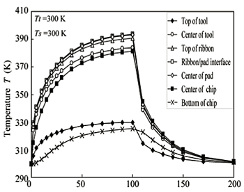
Figure 2 shows the calculated results of heat conduction (temperature T-change with time t at each position (A![]() G) along y axis of Fig. 1. The bottom of Si-chip and the tool top is assumed to be kept at 300 K. Because the heat input rate into the bond-interface is assumed to be constant during bonding, as can be seen in Fig. 1, the temperature monotonously increases at time t > 0 (after ultrasonic power is inputted) and decreases after t >100 s (ultrasonic power is turned off). It is suggested from the calculated results that Al ribbon heats up to 393K.
G) along y axis of Fig. 1. The bottom of Si-chip and the tool top is assumed to be kept at 300 K. Because the heat input rate into the bond-interface is assumed to be constant during bonding, as can be seen in Fig. 1, the temperature monotonously increases at time t > 0 (after ultrasonic power is inputted) and decreases after t >100 s (ultrasonic power is turned off). It is suggested from the calculated results that Al ribbon heats up to 393K.
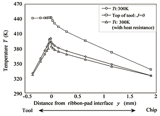
Figure 3 shows the temperature distributions at t = 100ms. If the top of tool is insulated (J = 0), the ribbon heats up higher. If the interfaces of tool/ribbon and pad/substrate have a heat resistance (conductivity of 1/10), then the Al ribbon can heat up to 402 K, but the heat resistance of the interfaces does not so largely affect the temperature rise of Al ribbon.
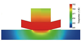
Figure 4 shows the temperature distribution map when the substrate is silica and Ts = Tt = 300K without heat resistance of the interfaces, where Ts and Tt are the temperatures at the chip-bottom and the tool-top, respectively. The Al ribbon is heated up as shown in Fig. 4. Because thermal conductivity of silica is very smaller (1/102) than that of silicon, Al ribbon heats up to 532K. The temperature at the bonding interface was measured experimentally. It was about 365![]() 370K during bonding. Actual temperature rise is about 100K at the highest.
370K during bonding. Actual temperature rise is about 100K at the highest.
Al ribbon is deformed as the temperature rises. The plastic deformation with strain rate dependence was simulated by assuming that the Al ribbon is kept at T = 373K, where T is an average temperature of ribbon. Figure 5 shows the equivalent stress distribution in the Al ribbon. Fig. 5 (a) is for free slip condition and Fig. 5(b) for the frictional slip condition. The equivalent stress is about P = 15 MPa, where P is the bonding pressure, although the stress is 28 MPa at the right edge of the tool. On the other hand, if the frictional slip occurs, the equivalent stress strikingly increases up to be 100 times greater than the bonding pressure. This is an ultrasonic vibration effect even if the ratio of vibration is 1/0.95 between top and bottom of ribbon. If the bonded interface is fixed and the displacement rate of the ribbon upper side is 1.88x10⁻² m/s, the equivalent stress is greater than 2000 MPa. As a result, a large plastic strain rate is produced by ultrasonic vibration (even if the ampritude of vibration is only 50 nm). It is suggested that the vibration after adhesion can break the sustrate and electric pad.
The ultrasonic bonding of Al ribbon is necessary for power electronics packaging technologies. Ultrasonic bonding process between wiring Al ribbon and pad on substrate is affected by ribbon deformation and thermal behavior (temperature rise of the materials during bonding). It was suggested that the temperature of ribbon rose up to be greater than 373 K during bonding. The ribbon deformation and the frictional slip behaviors influenced each other. The temperature distribution and stress distribution are to be visualized.
The main results are as follows;
1) Al ribbon heats up to about 373 K, if the ultrasonic power is less than 4W.
2) Heat resistance at the bond-interface does not have a large influence on the temperature rise.
3) Insulating or heating of the bonding tool is effective for heating Al ribbon.
4) Large stress is not obtained under the free slip condition.
5) Large stress is produced under the frictional slip or fixed conditions. This is understood as a softening effect of ultrasonic vibration. The ultrasonic vibration input after adhesion can give a hevey damage to the chip and the pad.


