In this study, samples of pure titanium were treated by gas nitriding using a rotary barrel tank in nominally pure nitrogen. For comparison, the samples were also subjected to commercial gas nitriding in nitrogen. The treatment time, flow rate of nitrogen gas, and the treatment temperature were varied systematically, and the effect of these process parameters on the formation of the modified layers was investigated. Cross-sectional microhardness depth profiles of the samples were obtained using a Vickers indenter. The surface morphology was observed using a scanning laser microscope. By means of X-ray diffraction (XRD) and electron-probe microanalysis (EPMA), the microstructure of the modified layer of the nitrided sample was analyzed. Here, we present our first report on the possibility of Ti nitriding that employs a barrel nitriding process.
Figure 1 shows a schematic diagram of the nitriding apparatus used in this study. A barrel that is usually used for plating or as an abrader was employed for titanium nitriding. Alumina powders were used as the media that flowed into the barrel tank. The average grain size of these powders was 100 ![]() m. The samples were first heated to a given temperature and were then nitrided during the oscillating movements of the barrel tank. The flow rate of the nitrogen ranged from 0.2 L/min to 3.0 L/min, and the treatment temperature ranged from 773 K to 1073 K. Nitriding was carried out for 3.6 ks to 32.4 ks. Pure titanium plates were used as samples for the nitriding process. The samples were cut into 30
m. The samples were first heated to a given temperature and were then nitrided during the oscillating movements of the barrel tank. The flow rate of the nitrogen ranged from 0.2 L/min to 3.0 L/min, and the treatment temperature ranged from 773 K to 1073 K. Nitriding was carried out for 3.6 ks to 32.4 ks. Pure titanium plates were used as samples for the nitriding process. The samples were cut into 30![]() 20
20![]() 1 mm3 pieces with a precision cutter. They were then polished using 240
1 mm3 pieces with a precision cutter. They were then polished using 240![]() 1500 grid SiC paper and then ultrasonically cleaned in an acetone bath.
1500 grid SiC paper and then ultrasonically cleaned in an acetone bath.
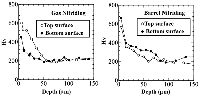
Figure 2 shows the hardness depth profiles of the top and bottom surfaces after both gas and barrel nitriding. With gas nitriding, there was a lower degree of hardness for the bottom surface than that for the top surface. The depth of the hard layers of the bottom and top surfaces was about 30 ![]() m and 55
m and 55 ![]() m, respectively. An inhomogeneous modified layer was formed on the bottom surface by the gas nitriding. With barrel nitriding, on the other hand, the hardness distributions of the top surface were roughly in accord with that of the bottom surface, which suggests that a uniform modified layer could be formed using barrel nitriding.
m, respectively. An inhomogeneous modified layer was formed on the bottom surface by the gas nitriding. With barrel nitriding, on the other hand, the hardness distributions of the top surface were roughly in accord with that of the bottom surface, which suggests that a uniform modified layer could be formed using barrel nitriding.
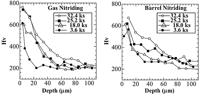
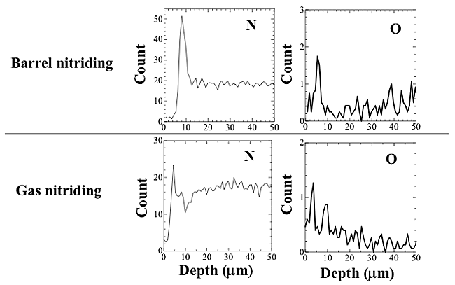
Figure 3 shows the effect of the hardness depth profiles on the treatment time with the use of both gas and barrel nitriding. With gas nitriding, no obvious differences in surface hardness were obtained between at 3.6 and 18.0 ks or at 25.2 and 32.4 ks, but as an overall trend, the treatment time tended to increase with an increase in surface hardness. The depth of the hard layer also increased with increasing treatment time. With barrel nitriding, there was a weak relationship between the treatment time and the surface hardness, and the relationship between the treatment time and the depth of the hard layer showed the same tendency as the results of the gas nitriding. We investigated the effect of the hardness depth profile on the flow rate of the nitrogen gas, and found that it had no discernible effect.These results apparently indicate that nitrogen diffused more readily into the sample using the barrel nitriding process, but to clarify these points, further investigation will be required. Line analysis of the hard layer was performed by EPMA. Figure 4 shows the results of the depth profiles of the elements N, and O at 18.0 ks at 1.5 L/min. With barrel nitriding, the peak of nitrogen was detected at a depth of 8 ![]() m beneath the outermost surface, and a small peak of the oxygen could be detected on the outermost surface. This result indicates that nitrogen was able to diffuse into the titanium samples in the case of barrel nitriding. Moreover, the increase in surface hardness shown in Fig. 3 is thought to be the result of this nitrogen diffusion. With gas nitriding, a small peak of nitrogen could be detected at a depth of 5
m beneath the outermost surface, and a small peak of the oxygen could be detected on the outermost surface. This result indicates that nitrogen was able to diffuse into the titanium samples in the case of barrel nitriding. Moreover, the increase in surface hardness shown in Fig. 3 is thought to be the result of this nitrogen diffusion. With gas nitriding, a small peak of nitrogen could be detected at a depth of 5 ![]() m, and the oxygen peak was also detected at a depth of 10
m, and the oxygen peak was also detected at a depth of 10 ![]() m from the surface. With barrel nitriding, the results suggest that an oxide layer was formed on the surface layer. The results of EPMA suggest that a compound layer of Ti and O was formed on the outmost surface. With gas nitriding, the results suggest that a diffusion layer of the oxygen was formed on the outermost surface because the peak of the oxygen gradually decreased.
m from the surface. With barrel nitriding, the results suggest that an oxide layer was formed on the surface layer. The results of EPMA suggest that a compound layer of Ti and O was formed on the outmost surface. With gas nitriding, the results suggest that a diffusion layer of the oxygen was formed on the outermost surface because the peak of the oxygen gradually decreased.
The consistent phase of the modified layer was investigated using XRD. With both gas and barrel nitriding, TiN, Ti2N, and Ti2O (or TiO2) were detected on the sample surface. The results of XRD showed no significant difference between the consistent phase of the hard layers obtained by gas and barrel nitriding. However, there is a clear difference between the crystal growth of the hard layer formed by gas nitriding and barrel nitriding, and we will study this difference in the future. In the results of the hardness depth profiles shown in Figs. 2 and 3, the surface hardness of the hard layer formed by gas nitriding had a higher value than that formed by barrel nitriding. It is thought that the surface hardness is affected by the residual stress, distribution of elements, ratio of the constituent phases, and other factors, but we are unable to discuss this with any definiteness at this time.


