This study proposes a form of indirect imaging of grains in polycrystalline materials on the basis of a high-resolution X-ray microtomography (XMT) technique. Grain boundary particles, which are often observed in high density in structural metals and alloys, are employed for the reconstruction of a given grain morphology as a high-dimensional polytope, typically with ![]() 100 vertices for each grain. With this technique, 4D deformation of each grain can be rendered, together with mapping of 4D local strain distribution. To confirm the feasibility of this technique, a high-resolution X-ray XMT technique has been used to obtain grain images in a wrought aluminium alloy. A detailed examination of the 4D characteristics of the crystallographic deformation behaviours is employed to discuss interactions among neighbouring grains during plastic deformation. The achievement of in situ observation of crystallographic deformation behaviours in 4D would be of significant value in the search for solutions to hitherto intractable problems in currently available model analyses.
100 vertices for each grain. With this technique, 4D deformation of each grain can be rendered, together with mapping of 4D local strain distribution. To confirm the feasibility of this technique, a high-resolution X-ray XMT technique has been used to obtain grain images in a wrought aluminium alloy. A detailed examination of the 4D characteristics of the crystallographic deformation behaviours is employed to discuss interactions among neighbouring grains during plastic deformation. The achievement of in situ observation of crystallographic deformation behaviours in 4D would be of significant value in the search for solutions to hitherto intractable problems in currently available model analyses.
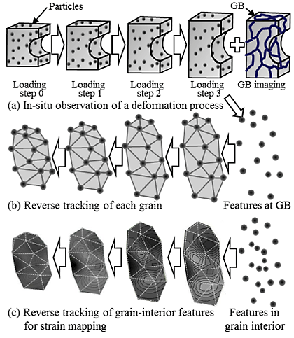
XMT can achieve 4D observation with reasonable spatial resolution and relatively large specimen size. As the first step in the grain boundary tracking (hereinafter GBT) process, the deformation behaviour of a miniaturised specimen is observed in situ in 4D with the XMT technique, as shown schematically in Fig. 1 (a). A specially designed test rig mounted on a rotation stage for XMT is usually utilised for the in-situ observation of the deformation and fracture process. The mechanical test must be interrupted before the final rupture occurs. The grain boundary wetting technique is then applied to the specimen, as shown in Fig. 1 (a) . The obtained set of binary grain boundary images is used for masking purposes, and the microstructural features are classified into grain boundary and grain interior with respect to their gravity centre locations. Each grain is reconstructed as a polygon mesh using the extracted microstructural features located along the grain boundaries. The polygon mesh actually represents the outer contour of a grain (i.e., the grain boundary). The aforementioned microstructural tracking technique is then applied both to the microstructural features located along the grain boundary and to those located in the grain interior. The deformation process of each polygonal grain is reproduced by tracking the microstructural features located along the grain boundaries, as shown in Fig. 1 (b). High-density 4D strain mapping is achieved by tracking the microstructural features located in the grain interior, enabling the assessment of inhomogeneous strain distribution in each grain.
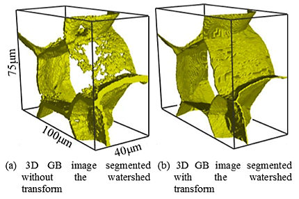
Figure 2 represents a typical example of the watershed-transform-treated image shown in 3D. It clearly demonstrates that an ill-segmented grain boundary which has only been partly reconstructed (roughly 50 % in this case) can be recovered successfully by optimising a few parameters in the segmentation processes.
The approximate shape of this grain can be visualised using these particles. Since this image consists of three-dimensionally connected triangles that express the outer contours of a given crystal grain, it can be volume-rendered.
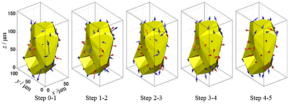
As described above, particles located in the grain interior have been used for measuring internal strain. The physical displacement of the vertices of each grain boundary polygon (which correspond to grain boundary particles), during external loading, are magnified and shown in Fig. 3. Large compressive (i.e., inward) and tensile (i.e., outward) displacements are observable on the grain boundaries. Clusters of arrows similar in direction and size indicate interfaces with neighbouring grains. Large generated strain may be observed in regions close to the grain boundary, corresponding to the large tensile displacement seen on the grain boundary in Fig. 3. It is reasonable to assume that such large strain concentration and grain boundary displacement arises from a mismatch in deformability among neighbouring grains. Grain boundary displacement also varies with loading, in a complex manner, sometimes resulting in a reversal of compression and tension. This may also be attributable to significant mutual interaction among neighbouring grains, which might vary with loading.
This study proposed a grain boundary tracking technique in which grain boundary particles are employed in the reconstruction of a given grain morphology as a high-dimensional polytope. 4D deformation of respective grains can be rendered below the medium temperature range, where grain boundary migration does not occur from initial grain boundary particles. With this technique, high density mapping of 4D local strain distribution is also achieved, which offers a robust tool for analysing localised strain distribution due to crystallographic deformation behaviour in polycrystalline materials.


